|


 |
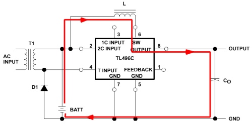
IntroductionThe first Battery Packs only contained a number of nickel-cadmium cells, each of which has a nominal voltage of 1.2 V. The calculator circuits operate on much higher voltages (up to 15 V) which were generated on the calculator main circuit board. So there was no electronics inside these BPs, and we will pay no special attention to them. Then, the voltage converter was built into the BP, as was the charging circuit. The first circuit, as found in the BP-5, was discrete and so big that it left space for a single cell only. Then, Texas Instruments developed an integrated circuit for this purpose (BP5IC-3A and BP5IC-4A). This chip was later released to the commercial market and called TL496. The original TI converter circuitWe will look into the principles of this circuit based on the TL496 datasheet. The explanations below are based on the block diagram on page 4-1 and the 2-cell application circuit on page 4-5. First, lets look at operation the calculator from the accumulators. The boost converter of the TL496 will step up the 2.4 V input voltage to 9 V using a very simple current-limited converter scheme.
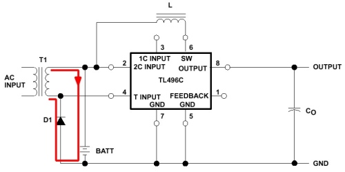
Whats happening if the accumulator is being charged? The positive half cycle of the AC voltage of the transformer is fed through the accumulators and charges them. Note that the current is limited by transformer resistance only.
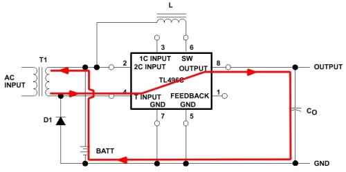
The negative half cycle is fed through the series regulator built into the TL496 and builds up the working voltage of the calculator at the output
capacitor. This voltage will be slightly higher than the threshold at which the step-up circuit begins to operate, thus effectively turning off switch-mode
operation. But the return current passes through the accumulators in reverse direction and cancels part of the charge the accumulators received in the
positive half cycle. If the calculator is operated while charging, the net charge the accumulators receive will be reduced.
Below, current flow into and out of the accumulators is shown while they are being charged.
|